Smartifying a Dumb Fan, and understanding the NEC protocol
Living in a dorm room with one AC unit per unit, not room, means that when my bedroom gets too hot from the computer running, I have to turn on a fan and open the door. I find myself constantly wishing for a thermostat, or at least some other way of automating it. As a computer scientist with an interest in computer engineering, I can’t help but feel like there’s a better way…
Well, as it just so happens, I have a Raspberry Pi running Home Assistant, which means that all I need to automate the fan is a temperature sensor, a microcontroller with Wi-Fi, and an infrared LED. One short AliExpress delivery later, by which I mean a few weeks, I have an ESP32-C3, AHT10 temperature/humidity sensor, IR LEDs and receivers, and a logic analyzer. As luck would (not) have it, the particular fan I have, the Woozoo SC15T, does not have a public list of IR codes to control it. It’s also somewhat complicated, as it oscillates in two axes, has a “breeze” mode, timers, and level adjustment. So that means I need a way to read IR codes, and figure out what IR communication protocol it’s using.
Reverse-Engineering The Remote
I figured the logical first step to reverse engineering the remote was to take it apart, to see how it worked. It’s composed of a sticker with pushbuttons on the back, the PCB, and the plastic housing.
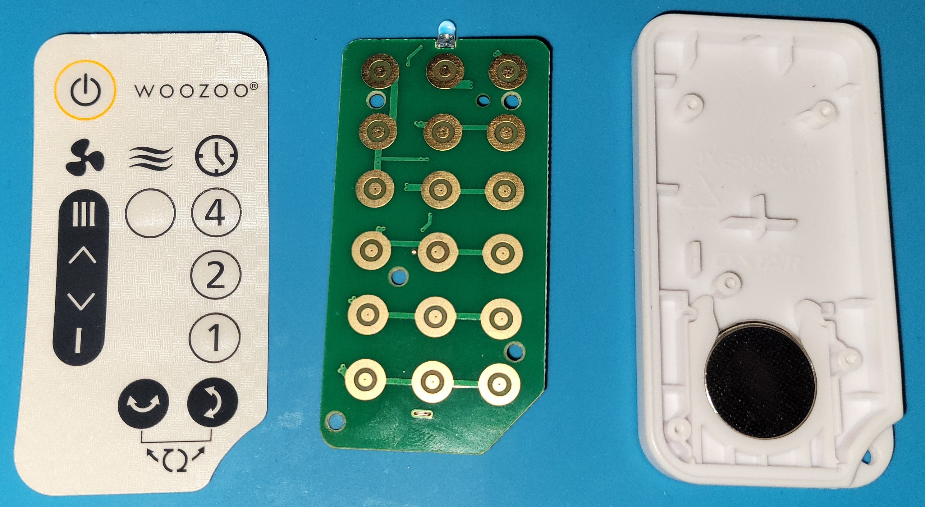
There’s something pretty interesting about this PCB. Can you spot it?
Yep, there are WAY more contacts on the PCB than there are actual buttons on the remote.
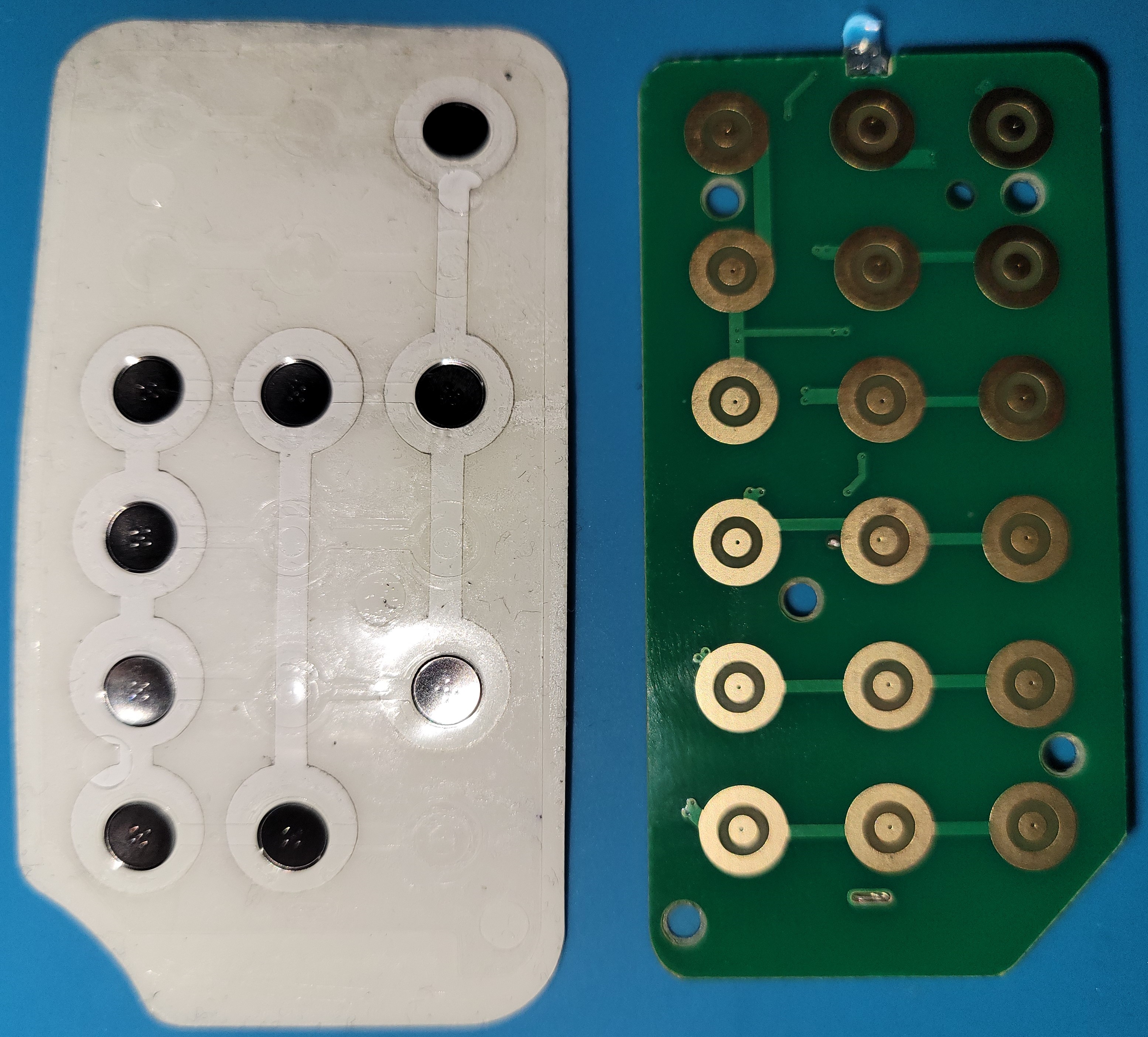
And you can actually see that the PCB traces are actually there, so they must actually do something… Activating them at my fan does (mostly) nothing, and I have a theory why, but we’ll get to that later.
Anyway, let’s take a look at the back…
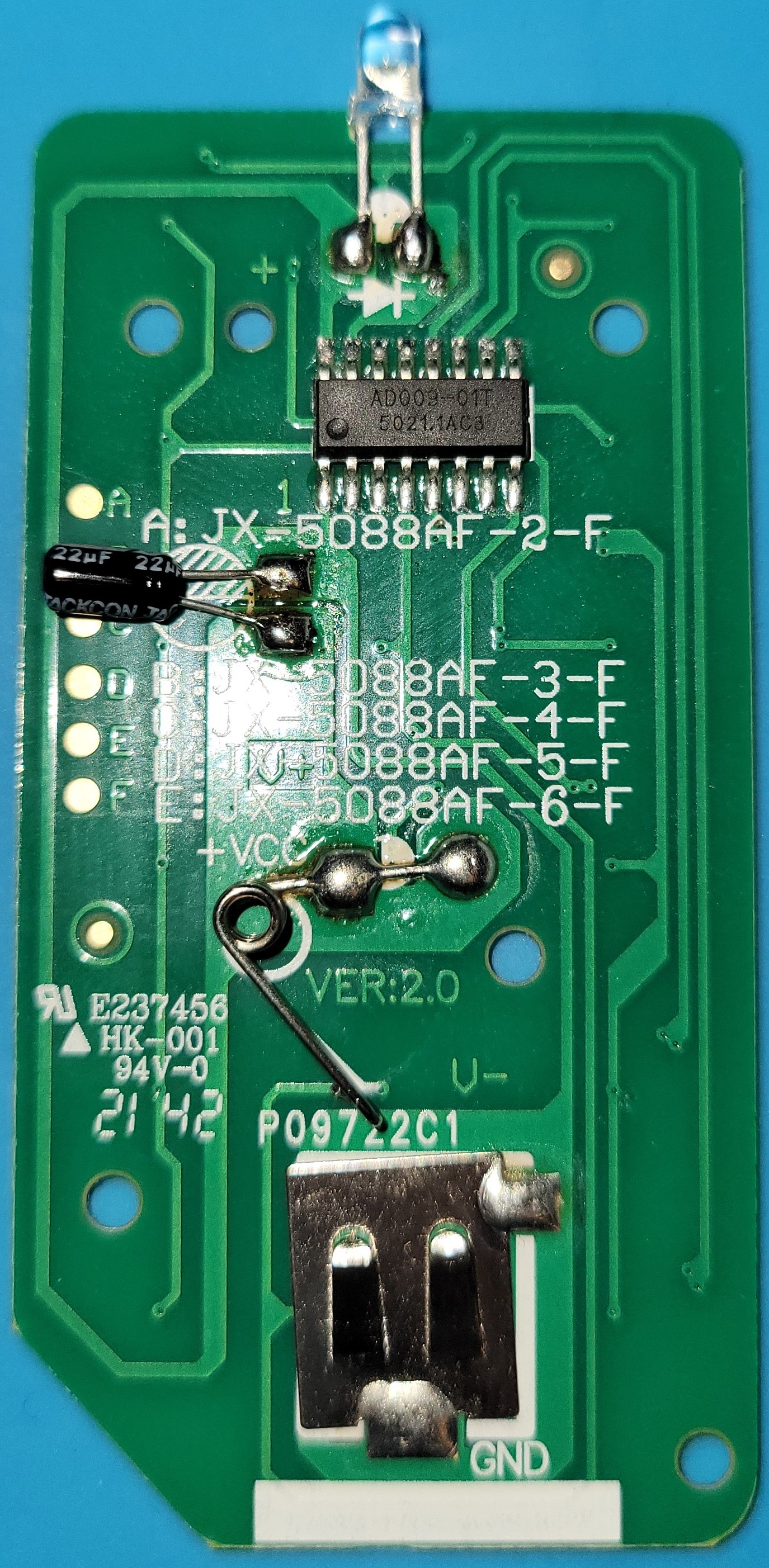
The only thing of note on there is the AD009-01T IR controller, which is to be expected. Looking at the datasheet doesn’t give me the protocol specifications or carrier frequency (which is another good sign it’s probably NEC), but it does tell me pin 15 is the IR output (which was already quite obvious from the PCB). I could probably attach my logic analyzer to pin 15 and manually decode signals, but I’d rather hook up an IR receiver to it so I can get rid of any PWM noise that may complicate things.
Reverse-Engineering the IR Signals
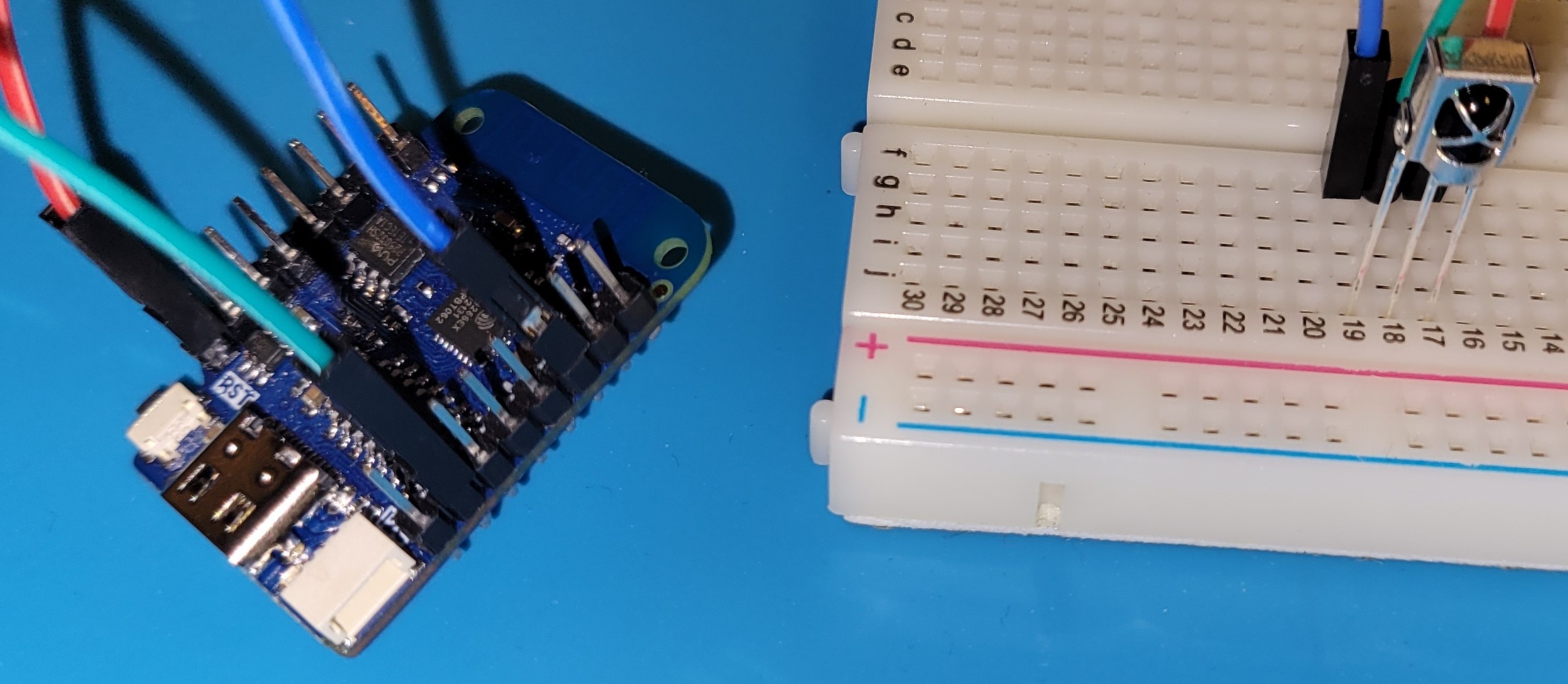
I decided to start off by assuming it’s using the NEC protocol with a carrier frequency of 38 KHz. It’s the most common protocol IR remotes use, and I didn’t see a particular reason why they’d go for anything else. So I wired up an IR receiver to the logic analyzer and used an old ESP8266 as a 3.3V power source.
After installing a plugin for NEC to Logic 2 and activating a button on the remote, I get this:
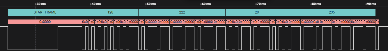
The NEC decoder at the top is really helpful, as it automatically decodes the data into base 10, but I’m going to break this down anyway.
NEC starts by transmitting a 9ms burst, then waiting 4.5ms before sending the real data. It uses short pulses as 0s and long pulses as 1s, and is split into 4 bytes, with the least significant bit first. It uses 2 bytes to send data: the device address and the command. It uses the form ADDR, NOT ADDR, CMD, NOT CMD where NOT means the logical inverse. Translating the above into binary as it is produces this:
00000001 01111011 00101000 11010111
Reversing the bits so that the most significant bit is first (the norm for most computers) we get this:
10000000 11011110 00010100 11101011
…or 0x80DE14EB for short. If it’s using the original NEC protocol, the second byte should be the logical NOT of the first, but it’s not! Which is actually completely normal, because the Extended NEC protocol changes the form to ADDR[1], ADDR[0], CMD, NOT CMD to support more devices and reduce address collisions. This lets us makes sense of this data in hex:
ADDR[1] = 0x80
ADDR[0] = 0xDE
CMD = 0x14
… and the checksum of CMD can be verified with:
NOT CMD = 0xEB
Yay! That’s a valid Extended NEC code. The addresses are also organized from least significant bit, which means that the address is really 0xDE80. That’s all we need for the NEC protocol: the address and the command. So I went ahead and captured every button’s output and put it in a table:
| Column 1 | Column 2 | Column 3 |
|---|---|---|
| 0x0 | 0x1 | 0x2 |
| 0x4 | 0x5 | 0x6 |
| 0x8 | 0x9 | 0xA |
| 0xC | 0xD | 0xE |
| 0x10 | 0x11 | 0x12 |
| 0x14 | 0x15 | 0x16 |
There’s a pretty clear pattern. These can be pretty easily mapped to the sticker buttons:
| Command | Description |
|---|---|
| 0x0 | Power toggle |
| 0x8 | Increase speed |
| 0x10 | Decrease speed |
| 0x9 | Breeze Mode |
| 0x15 | Horizontal Oscillation |
| 0x16 | Vertical Oscillation |
| 0x12 | 1 Hour Timer |
| 0xE | 2 Hour Timer |
| 0xA | 4 Hour Timer |
| 0x2 | Emergency Stop |
Oh yeah, there’s an emergency stop. This isn’t usually accessible on the remote, I discovered it accidentally when I activated the button on the opposite side of the power button. The fan beeped really loudly for a few seconds then stopped, so I’m assuming it’s an emergency stop, but I don’t actually know if that’s what it does. Maybe it resets the fan controller or something? I also discovered that the remote does in fact produce other IR commands, but my fan refuses to acknowledge them. As it turns out, my fan has a sibling called the C15T. The remotes look remarkably similar, but with different buttons, so I’m guessing that they use the same PCB with different stickers and buttons to save cost and make production easier.
Make It Smart with ESPHome
ESPHome is firmware for ESP32, ESP8266, and RP2040 that can control & send data to Home Assistant. Using it, we can log temperature & humidity data from an attached sensor, which I can then access on my phone, and it can give me a button to activate the fan by controlling an IR LED. Home Assistant has automations which will let me turn on the fan or turn it off when the temperature reaches a certain point, too. But first, we need to load ESPHome onto the microcontroller. ESPHome uses a configuration YAML file to figure out which features to enable and how, so here’s the one that I used:
esphome:
  name: esphome
  friendly_name: ESPHome
  platformio_options:
    board_build.flash_mode: dio

esp32:
  board: lolin_c3_mini
  framework:
    type: esp-idf

# Enable logging
logger:

# Enable Home Assistant API
api:
  encryption:
    key: "**********"

ota:
  password: "**********"

wifi:
  ssid: "**********"
  password: "**********"

  # Enable fallback hotspot (captive portal) in case wifi connection fails
  ap:
    ssid: "Wi-Fi Fallback Hotspot"
    password: "**********"

# The sensor communicates with I2C so it needs to be enabled
i2c:
  scan: true

sensor:
  - platform: aht10
    temperature:
      name: "Temperature"
    humidity:
      name: "Humidity"
    update_interval: 60s

# The lolin c3 mini has a small neopixel on the board
light:
  - platform: esp32_rmt_led_strip
    rgb_order: GRB
    pin: 7
    num_leds: 1
    rmt_channel: 1
    chipset: ws2812
    name: "Onboard LED"
    restore_mode: RESTORE_DEFAULT_OFF
    id: status

# The lolin c3 mini has a button connected to pin 9
binary_sensor:
  - platform: gpio
    pin:
      number: GPIO9
      inverted: true
      mode:
        input: true
        pullup: true
    name: "Button"
    on_press:
      then:
        - light.toggle: status

# There's an IR LED connected to GPIO5
remote_transmitter:
  pin: GPIO5
  carrier_duty_percent: 50%

# https://esphome.io/components/remote_transmitter.html
button:
  - platform: template
    name: "Woozoo Fan Toggle"
    on_press:
      remote_transmitter.transmit_nec:
        address: 0xDE80
        command: 0xFF00
  - platform: template
    name: "Woozoo Fan Increase Speed"
    on_press:
      remote_transmitter.transmit_nec:
        address: 0xDE80
        command: 0xF708
  - platform: template
    name: "Woozoo Fan Decrease Speed"
    on_press:
      remote_transmitter.transmit_nec:
        address: 0xDE80
        command: 0xEF10
  - platform: template
    name: "Woozoo Fan Breeze Mode"
    on_press:
      remote_transmitter.transmit_nec:
        address: 0xDE80
        command: 0xF609
  - platform: template
    name: "Woozoo Fan Horizontal Oscillation"
    on_press:
      remote_transmitter.transmit_nec:
        address: 0xDE80
        command: 0xEA15
  - platform: template
    name: "Woozoo Fan Vertical Oscillation"
    on_press:
      remote_transmitter.transmit_nec:
        address: 0xDE80
        command: 0xE916
  - platform: template
    name: "Woozoo Fan Timer 1 Hour"
    on_press:
      remote_transmitter.transmit_nec:
        address: 0xDE80
        command: 0xED12
  - platform: template
    name: "Woozoo Fan Timer 2 Hours"
    on_press:
      remote_transmitter.transmit_nec:
        address: 0xDE80
        command: 0xF10E
  - platform: template
    name: "Woozoo Fan Timer 4 Hours"
    on_press:
      remote_transmitter.transmit_nec:
        address: 0xDE80
        command: 0xF50A
You can read the ESPHome docs for more detail but this configuration file is pretty self explanatory.
I connected everything together, and flashed the ESPHome firmware.
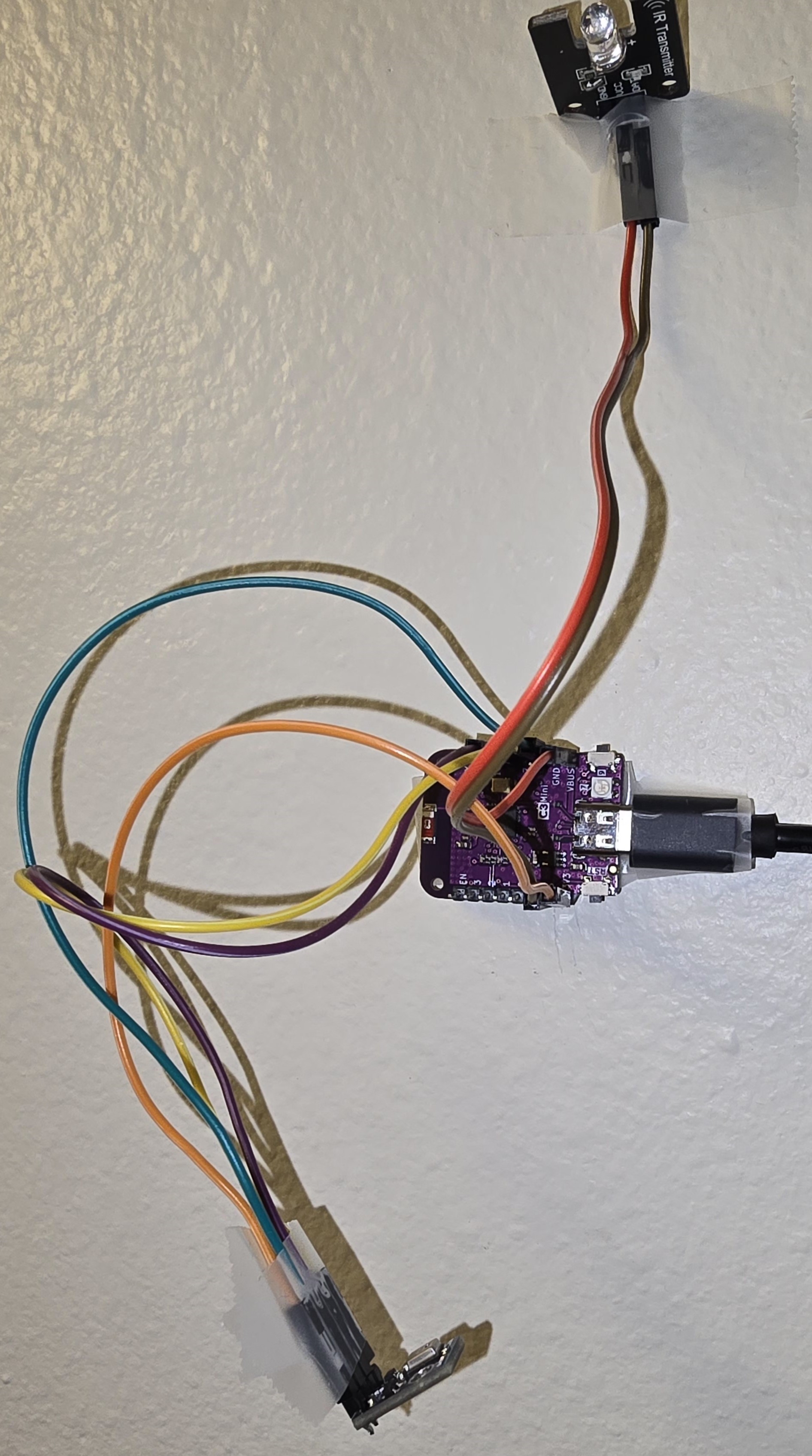
(Ignore the missing ground wire, I borrowed it for something else.)
Then, I added it to Home Assistant.
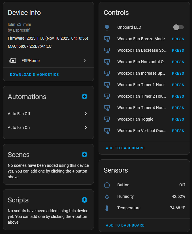
I made some automations to turn the fan on or off based on the temperature, and voila! It’s that easy.
It works reasonably well, except for the fact that it’s a jumbled mess of wires precariously taped to my wall. Not to be outdone by gravity, me suddenly tripping and disconnecting everything, or a sudden need to borrow jumper wires, I’ve designed and ordered a PCB that connects everything together nicely. It also uses a cheaper and smaller ESP32 design that can be found on AliExpress for only $2.
Join me next time as I learn to use KiCad and figure out if I can design a carrier PCB for the sensors and microcontroller or skip the IR entirely and stuff this thing inside my fan. (Probably not that last part, I don’t think I want to mess with high voltage).
Share on
X Facebook LinkedIn Bluesky
Acceptable Advertisement
Comments